

Description
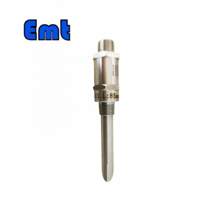
Name | Chemical Injection System Access Fitting | |
| Material | Stainless Steel 304, Stainless Steel 316, DSS F51, Carbon Steel A105N, and also Inconel 625 | |
| Operating Temperature | -20±120 | |
| Feature | Firstly, easy Operating | |
| Secondly, high Accuracy Long Life | ||
| At last, high Efficiency, Low cost | ||
| Payment | TT/LC | |
| Advantage | Firstly, they are lightweight and flexible. | |
| Secondly, excellent Injection efficiency. | ||
| At last, accurate location tracking. |

| Model | ||||||||||||||||||||||||||||
SI | Chemical Injection System Access Fitting | |||||||||||||||||||||||||||
| -Code | Plug | |||||||||||||||||||||||||||
| Pxxx | Type | Material | Sealing Material | |||||||||||||||||||||||||
| 0 | No Request | 0 | CS | 0 | No Request | |||||||||||||||||||||||
| 1 | Hollow Plug Body | 1 | 316SS | 3 | DSS | 1 | Viton O-Ring / PTFE Primary Packing | |||||||||||||||||||||
| 2 | Solid Plug Body | 2 | 316LSS | 4 | INCONEL | 2 | HNBR | |||||||||||||||||||||
| – Code | Injection Nut | |||||||||||||||||||||||||||
| Nxx | Connection Size | Material | ||||||||||||||||||||||||||
| 0 | i.e. No Request | 0 | i.e. CS | |||||||||||||||||||||||||
| 1 | i.e. 1/4″ | 1 | i.e. 316SS | 3 | i.e. DSS | |||||||||||||||||||||||
| 2 | i.e. 1/2″ | 2 | i.e. 316LSS | 4 | i.e. INCONEL | |||||||||||||||||||||||
| – Code | Injection Tube | |||||||||||||||||||||||||||
| Sxxx-Lx″ | Connection Size | Material | Nozzle | Line size(x″) | ||||||||||||||||||||||||
| 0 | No Request | 0 | CS | 0 | i.e. No Request | The most effective position for injection is generally at the center of the pipe | ||||||||||||||||||||||
| 1 | i.e. 1/4″ | 1 | i.e. 316SS | 1 | i.e. Open | |||||||||||||||||||||||
| 2 | i.e. 1/2″ | 2 | i.e. 316LSS | 2 | i.e. Quill | |||||||||||||||||||||||
| 3 | i.e. DSS | 3 | i.e. Cap & Core | |||||||||||||||||||||||||
| 4 | i.e. INCONEL | |||||||||||||||||||||||||||
| – Code | Nipple and Valve(or end Flange)of the Tee | |||||||||||||||||||||||||||
| Txx | Connection Size | Material | ||||||||||||||||||||||||||
| 0 | i.e. No Request | 0 | i.e. CS | |||||||||||||||||||||||||
| 1 | i.e. 1/4″Nipple | a | i.e. 1/4″Nipple and Valve | 1 | i.e. 316SS | |||||||||||||||||||||||
| 2 | i.e. 1/2″Nipple | b | i.e. 1/2″Nipple and Valve | 2 | i.e. 316LSS | |||||||||||||||||||||||
| 3 | i.e. 3/4″Nipple | c | i.e. 3/4″Nipple and Valve | 3 | i.e. D SS | |||||||||||||||||||||||
| 4 | i.e. 1″Nipple | d | i.e. 1″Nipple and Valve | 4 | i.e. INCONEL | |||||||||||||||||||||||
| 5 | i.e. 1/4″Flange | e | i.e. 1/4″Nipple end Flange | |||||||||||||||||||||||||
| 6 | i.e. 1/2″Flange | f | i.e. 1/2″Nipple end Flange | |||||||||||||||||||||||||
| 7 | i.e. 3/4″Flange | g | i.e. 3/4″Nipple end Flange | |||||||||||||||||||||||||
| 8 | i.e. 1″Flange | h | i.e. 1″Nipple end Flange | |||||||||||||||||||||||||
| For Example, SI-P221-N12-S122-L4″-T22 SI:e.g. Sampling & Injection Assembly, P221: e.g. Solid Plug Body in 316LSS Viton O-Ring and PTFE Primary Packing, N12:e.g. injection Nut Connection Size is 1/4″and Material is 316LSS, S122:e.g. injection Tube Connection Size is 1/4″ and Material is 316LSS.The type of nozzle is quills L4″:For 4″pipe. T22: Nipple of Tee Connection Size is 1/2″, Nipple material is 316LSS | ||||||||||||||||||||||||||||
The chemical reagent injection system
A chemical reagent injection system is a device commonly used to inject quantitative chemical reagents such as methyl glycol, ethylene glycol, corrosion inhibitor, and antifreeze into oil and gas wells in oil gas exploitation. It can be unblocked and thawed. It is a device to restore the wellhead to regular operation.
Other uses: the system injects quantitative liquid chemicals underrated pressure. (the medium can be antiseptic, deoxidant, flocculant, defoamer, scale inhibitor, corrosion inhibitor, drilling fluid additive, etc.). It can be used in chemical plants, power plants, oil refineries, oil and gas exploration, and offshore drilling platforms. Unblocking and thawing of pipelines and nozzles in water treatment plants and other environments. It can also meet the problems of scaling, asphaltene treatment, and emulsification. There are also natural gas hydrate problems, foaming problems, and paraffin treatment. Purification treatment, corrosion problems, and other process requirements. It can also be used to quantitatively fill reaction raw materials into the high-pressure reactor.
Main characteristics of chemical reagent injection system:
- Applicable to offshore and land platform environments;
- This ensures the smoothness of the flow channel. It can effectively reduce the high workover cost caused by channel blockage. This can ensure better oil products;
- Provide manual or automatic pressure flow control mode
- Provide pneumatic, electric, solar and other driving modes according to different application environments;
- Provide non-standard customization
The chemical reagent injection system is mainly used to inject methanol or ethylene glycol into the fluid upstream of oil and gas wells, pipelines, or oil nozzles in oil exploitation, It can prevent formation flow from freezing hydrate due to pressure drop. This also increases the pressure drop range above and below the nozzle. It makes the oil (gas) well resume normal production. The chemical injection system is relatively simple. Its suction end is a pneumatic plunger pump. The pump is connected to the container of the chemical agent. And its discharge end is directly connected to the pipeline.
Main features of the equipment
The chemical injection pump system includes ultra-high pressure hydraulic, mechanical, and driving gas. The hydraulic part provides an ultra-high pressure source for the chemical injection system. The driving gas part provides the power source for the whole system. The drive circuit is a pneumatic circuit. The medium is clean natural gas. This can avoid the disadvantages such as leakage of hydraulic pressure or expensive power. It uses on-site natural gas to make its operation more economical and save costs. At the same time, it is driven by on-site gas and does not need electricity. There will be no sparks, so it is safe and explosion-proof.
The high-pressure circuit is a hydraulic circuit. The medium is clean methanol/ethylene glycol. The system uses a gas-drive liquid pump to provide a pressure source. When the system pressure is lower than the set value, the gas drive liquid pump can make up in white. A pneumatic chemical injection pump can easily realize any adjustable and controllable output pressure and flow




Reviews
There are no reviews yet.